
You have a car with left and right radar sensor at … Task Two: The JK Flip-Flop 1. The JK flip flop is one of the most used flip flops in digital circuits. Dari Tabel Kebenaran di atas dapat dijelaskan bahwa JK Flip flop berarti memberikan respons output terhadap input-input sinkronnya, jika nilai logika PRE dan CLR keduanya adalah "1", apabila PRE=1 maka output=0, sedangkan jika CLR=1 maka output=1. Figure 5: Mealy State Machine Circuit Implementation Timing Diagram for the circuit is shown in Figure 6. Every JK Flip Flop output consider as the output bit which makes the total 4 bits here. D-type edge … Truth tables are not always the best method for describing the action of a sequential circuit such as the SR flip-flop. Halimbawa, sa ibinigay na pigura sa ibaba, maaari naming makita ang isang senyas ng pulso ng SR flip-flop is one of the fundamental sequential circuit possible. A master-slave flip -flop consists of two flip-flops, one serving as a master, one serving as a slave and an inverter for the clock pulse.Draw the output versus time at each of the points specified in the diagram below. Use K-map to derive the flip flop reset input functions. The sequential operation of the JK Flip Flop is the same as for the RS flip-flop with the same SET and RESET input.

Jk negative edge triggered flip flop waveform full#
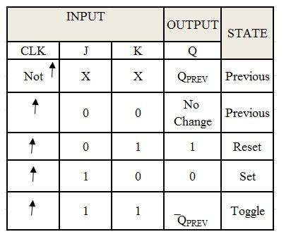
Fig: Timing Diagram of D Flip flop The DSCH timing diagram represents the CMOS Full swing circuit. J K To avoid having a flip-flop change values during the life of a clock pulse, it is important to have the flip-flop respond to either positive or negative edge only. There arises a new problem in JK flip flop, when J and K inputs of the JK flip flop are provided with high input i. Mainly I am curious about the storage process but I have not found anything in the web. When J = K = 0, it holds its present state. Develop characteristic table for JK flip-flop. In addition to the basic input-output pins shown in Figure 1, J K flip-flops can also have special inputs like clear (CLR) and preset (PR) (Figure 4 The JK flip-flop has two inputs labeled J and K. Perubahan pada negatif edge di masing-masing clock flip-flop sebelumnya menyebabkan flip-flop sesudahnya berganti kondisi (toggle), sehingga input-input J dan K di masing-masing flip-flop … Master Slave Flip Flop Timing Diagram. Elec 326 21 Flip-Flops Draw a timing diagram for this circuit assuming that the propagation delay of the latch is greater than the clock pulse width. The circuit diagram of JK flip-flop is shown in the following figure. 8 Truth table for a negative edge-triggered UK flip-flop Preset Clear СК J K Q 0 X 7) Using the 74LS76 dual JK flip flop, determine its logical operation. It is considered to be a universal flip-flop circuit. The upper switch is 'J'(SET), The lower switch is 'K'(RESET), The push button is 'CLK' (CLOCK PULSE). The lowest-order bit Q 0 It is set by output of flip-flop U which has output Q = 0. We have also assumed that the counter is in state Q 1 Q 0 = 00 in the clock cycle 0.

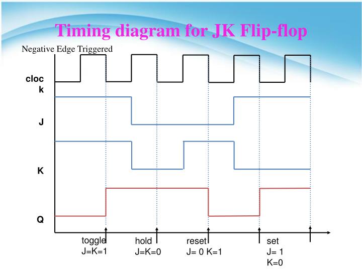
In SR flip flop, the ‘S’ and ‘R’ are the shortened abbreviated letters for Set and Reset, but J and K are not. When high, they override the clock and data inputs forcing the outputs to the steady state levels. We will assume an initial condition (T 0) of Q being LOW and Q being HIGH. Assume that the input signal can change only on the vertical lines. As you already know, when J, K and Clock are equal to 1, toggling takes place. Since the toggle from high to low to high takes two clock cycles, the output frequency will be half of the clock frequency. 3 shows a flip-flop and its corresponding timing diagram. (08 Marks) Design asynchronous counter for the sequence 0 -¥ 4 -¥ 1 -¥ 2 -¥ 6 0 -¥ 4, using (12 Mariks)Ô flip-flop. I'm wondering how a timing diagram for a positive triggered master/slave d flip flop looks like. This circuit has two inputs J & K and two outputs Q(t) & Q(t)’. JK Flip Flop Timing Diagram This is known as a timing diagram for a JK flip flop. If J and K are different then the output Q takes the value of J at the next … JK Flip Flop Timing Diagram This is known as a timing diagram for a JK flip flop. Design a combinational logic circuit given the following description of the required circuit function. SR master-slave flip-flop timing diagram Edge Triggered Flip-Flop. Complete the following timing diagram of the JK flip-flop Set the initial Q value as Low 9. Jk flip flop timing diagram Outputs Q and Q’ are the usual normal and complementary outputs.


 0 kommentar(er)
